Cp and Rp effectively limit the maximum data rate which can be transferred over SDA and SCL. A high Cp can be compensated with a low Rp and vice versa.
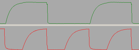
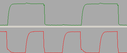
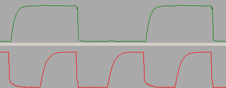
The following three pictures show the same part of an I2C transfer. Compared to the first one, the second picture shows the signals with a modified Rp of 2 kΩ, the third one with a lower Cp of 150 pF.
Note: Long wires increase Cp dramatically. I2C connections should always be as short as possible and connected by a suitable wiring pattern (c.f. I2C specification, section 17.3).

- SDA (above) and SCL (below) with Rp = 10 kΩ and Cp = 300 pF. The SCL clock runs with 100 kHz (nominal).

- The same transfer as above, but this time with a reduced termination resistance (Rp = 2 kΩ, Cp = 300 pF)

- The same transfer as above, but this time with a reduced wire capacitance (Rp = 10 kΩ, Cp = 150 pF)
Note that the I2C standard limits Cp to the maximum value of 400 pF. However, with an appropriate termination resistance, it is often possible (although not recommended) to operate I2C buses with higher capacitance.
<< How I2C Hardware WorksTermination Versus Serial Resistance >>
