
The I2C bus transmits data and clock with SDA and SCL. The first thing to realize: SDA and SCL are open-drain (also known as open-collector in the TTL world), that is I2C master and slave devices can only drive these lines low or leave them open. The termination resistor Rp pulls the line up to Vcc if no I2C device is pulling it down. This allows for features like the concurrent operation of more than one I2C master (if they are multi-master capable) or stretching (slaves can slow down communication by holding down SCL).
Together with the wire capacitance Cp, the termination resistor Rp affects the temporal behaviour of the signals on SDA and SCL. While I2C devices pull down the lines with open drain drivers or FETs which can in general drive at least about 10mA or more, the pull-up resistor Rp is responsible for getting the signal back to high level. Rp commonly ranges from 1 kΩ to 10 kΩ, resulting in typical pull-up currents of about 1 mA and less. This is the reason for the characteristic sawtooth-like look of I2C signals. In fact, every ‘tooth’ shows the charge characteristic of the line on the rising edge and the discharge characteristic on the falling edge.
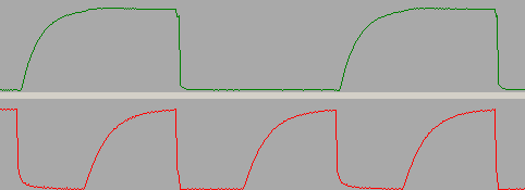
SDA (above) and SCL (below) with Rp = 10 kΩ and Cp = 300 pF. The SCL clock runs with 100 kHz (nominal).